Instruction Manual
-
Introduction
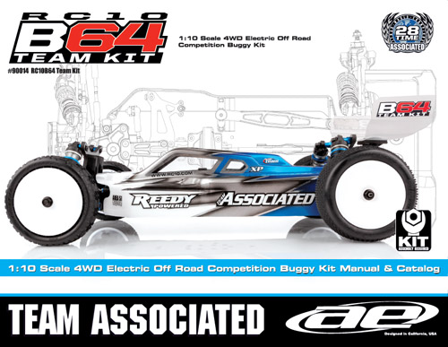
Thank you for purchasing this Team Associated product. This assembly manual contains instructions and tips for building and maintaining your RC10B64. Please take a moment to read through the manual and familiarize yourself with the steps. We are continually changing and improving our designs; therefore, actual parts may appear slightly different than the illustrations. New parts will be noted on supplementary sheets located in the appropriate parts bags. Check each bag for these sheets before you start to build.
These notes are from the 2/2017 version of the manual.
Parts shown are those in the printed manual. Optional parts are available. See the Parts List page in this app and choose "FT and Option Parts." -
RC10B64 Kit Features
It all started with a 1-2-3 sweep. In 2007, the RC10B44 swept the podium at the I.F.M.A.R. World Championships. Since then, Team Associated's first 1:10 scale 4WD buggy has held a dominant place at the front of the field. The B44 platform as gone on to win numerous National and International titles and added two more I.F.M.A.R. World Championships to its legacy in 2011 and 2013.
Speed, grip, and durability. Designed to take advantage of today's faster-than-ever tracks, the RC10B64 Team Kit offers increased durability, all-new suspension geometry, a wider tuning window, improved weight distribution, and easy maintenance. Excelling on dirt and clay surfaces, the B64's adjustable axle height and roll centers result in a stable yet nimble platform. The new center slipper clutch allows for later braking and enhanced on-power acceleration out of the corners.
Additional RC10B64D Team Kit Features:- V2 12mm Big Bore threaded aluminum shocks with 3mm TiN coated shafts and low-friction X-rings for improved smoothness
- Factory Team floating aluminum motor mount and aluminum/carbon servo mounts
- Refined arm mount geometry with quick-and-easy tuning
- Front and rear anti-roll bars keep chassis flat for increased corner speed
- Narrow, 7075 hard-anodized aluminum chassis with centralized mass
- Easy-access center slipper clutch
- Strengthened front and rear suspension with hard-anodized aluminum caster blocks and graphite shock towers
- Team Associated clear body and screw-mounted wing by JConcepts™
- All metric hardware throughout
-
Helpful Items Needed
For parts required, see here: Required
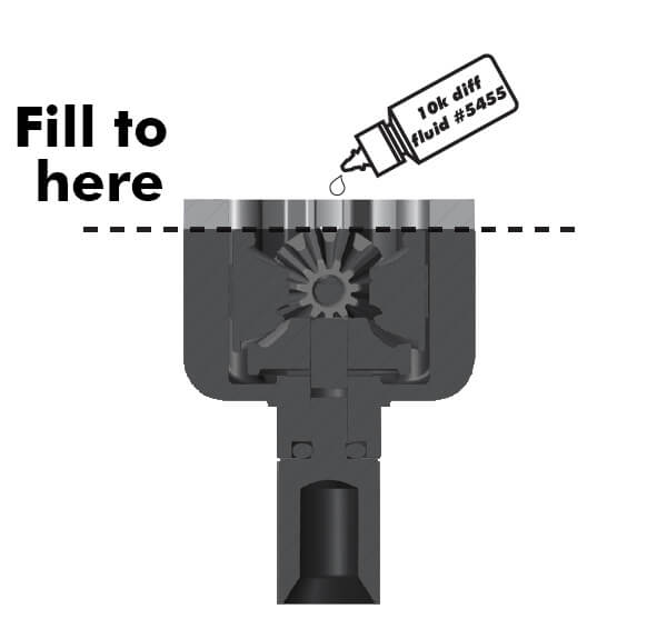
topOnline Item Fluids Silicone Shock Fluid Fluids Silicone diff Fluid #1737 Body Scissors (AE Part # 1737) #1675 Shock Shaft Pliers (#1675) #1519 FT Hex and Nut Wrenches (AE Part #1519) #1596 Threadlock (AE Part # 1596) #1105 Green Slime shock lube (AE Part # 1105) Reamer / Hole Punch Wire Cutters Needle Nose Pliers Hobby Knife Soldering Iron Calipers or a Precision Ruler -
Symbols Used
 This symbol indicates a special note or instruction in the manual.
 This symbol indicates a Racer's Tip.
 -
Abbreviations Used
You'll see the following abbreviations used in this app.
Online Name AE Associated Electrics, Inc., Team Associated's legal name BHCS Button Head Cap Screw CA Cyanoacrylate glue, otherwise known as super glue (in parts list) cSt Centistokes, a measure of fluid viscosity (in parts list) CVA Constant Velocity Axle Diff Differential FHCS Flat Head Cap Screw FT Factory Team FWD Forward HD Heavy Duty (in parts list) HRC High Roll Center IFMAR International Federation of Model Auto Racing, race sanction organization LCF Low Coefficient Friction, for center slipper pads LiPo Lithium Polymer, battery type LRC Low Roll Center LP Shorty Low Profile Shorty (in parts list) ROAR Remotely Operated Auto Racing, race sanction organization (in parts list) SHCS Socket Head Cap Screw SS Short Stack, motor with more rpm (in parts list) TiN Titanium Nitride, a shock shaft coating 2M/2F 2 Male/2Female plugs (in parts list) VTS Variable Torque, multi-plate Slipper with 3 drive surfaces V2 version 2 wt weight, such as 30wt for shock fluid viscosity -
Bag 1, Gear Diff, front and rear
Bags 1.1-1.3 step 1
 top
Show/Hide Parts
Online Name 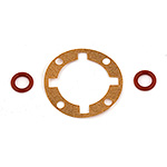
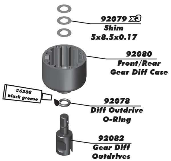
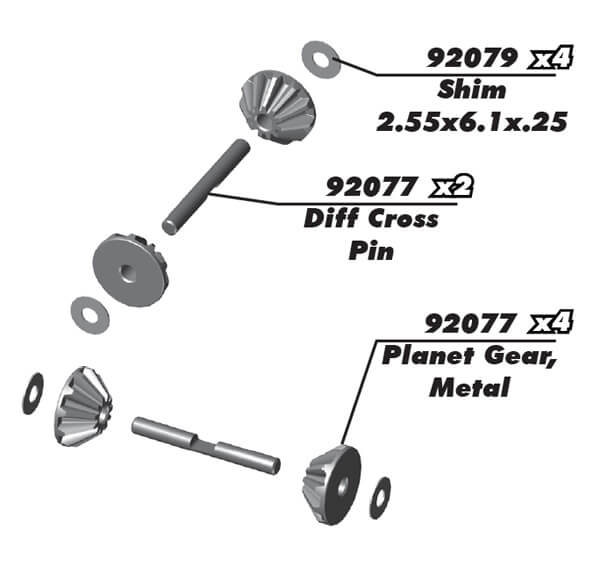
#92078 B64 Diff Gasket and O-Rings 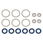
#92079 B64 Diff Shims 
#92080 B64 Diff Cases, for front, center, rear 
#92082 B64 Gear Diff Outdrives 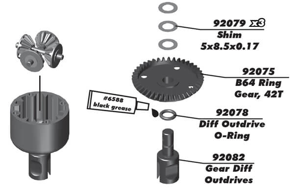 Show/Hide Parts
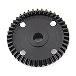
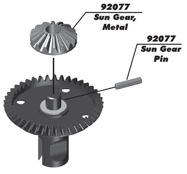
#92075 B64 Ring Gear, 42T 
#92078 B64 Diff Gasket and O-Rings 
#92079 B64 Diff Shims 
#92082 B64 Gear Diff Outdrives 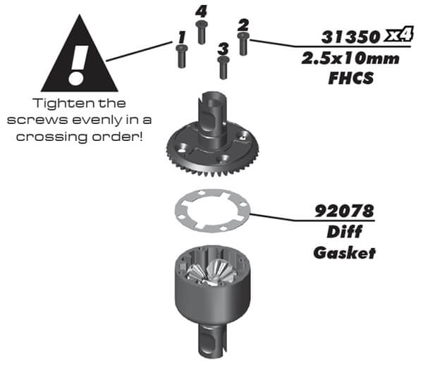
B64 manual shows #31448 2.5x8mm FHSC used.
top Show/Hide Parts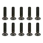
#31350 Screws, 2.5x10 mm FHCS 
#92078 B64 Diff Gasket and O-Rings -
Bag 1, Slipper Clutch
Bags 1.1-1.3 step 4
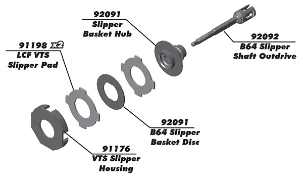
VTS = Variable Torque, multi-plate Slipper with 3 drive surfaces.
top Show/Hide Parts
LCF = Low Coefficient Friction.Online Name 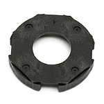
#91176 VTS Slipper Housing 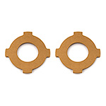
#91198 LCF VTS Slipper Pads 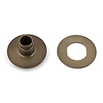
#92091 B64 FT Slipper Basket Hub 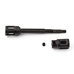
#92092 B64 FT Slipper Shaft/Outdrive 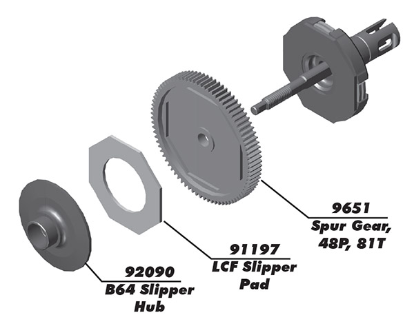
LCF = Low Coefficient Friction.
top Show/Hide PartsOnline Name 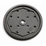
#9651 Spur Gear, 81T 48P 
#91197 LCF Slipper Pads 
#92090 B64 FT Slipper Hub Bags 1.1-1.3 step 5
 top
Show/Hide Parts
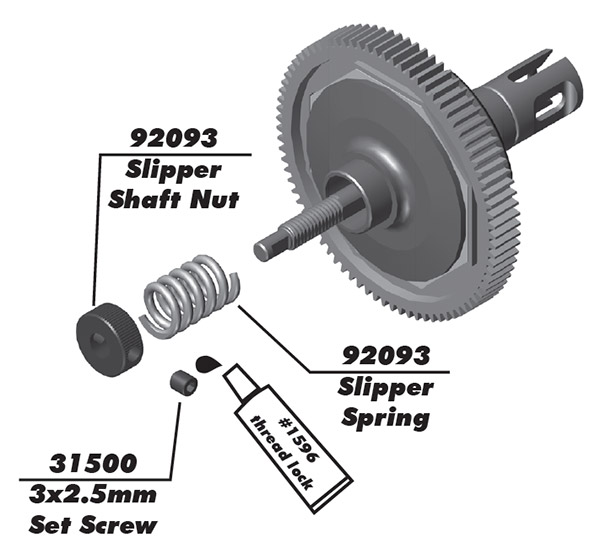
Online Name 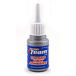
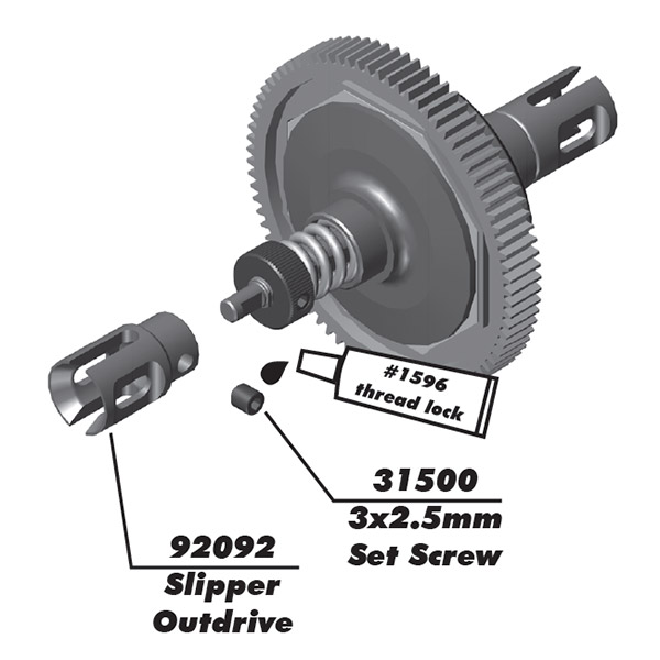
#1596 FT Locking Adhesive 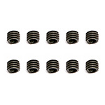
#31500 Set Screws, 3x0.5x2.5 mm 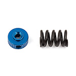
#92093 B64 FT Slipper Nut 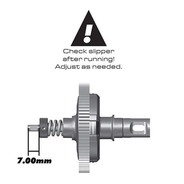
 top
Show/Hide Parts
Online Name 
#1596 FT Locking Adhesive 
#31500 Set Screws, 3x0.5x2.5 mm 
#92092 B64 FT Slipper Shaft/Outdrive -
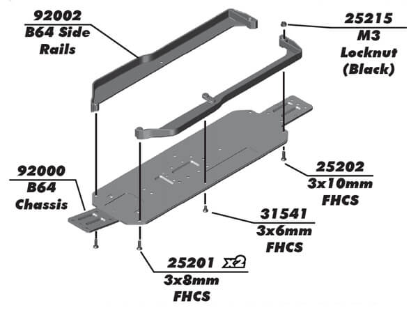
Bag 2, Chassis
 top
Show/Hide Parts
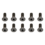
#25201 Screws, 3x8 mm FHCS 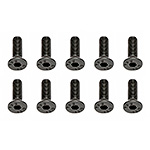
#25202 Screws, 3x10 mm FHCS 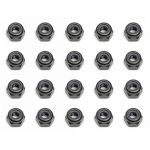
#25215 Locknuts, M3 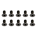
#31541 Screws, 3x0.5x6 mm FHCS 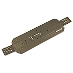
#92000 B64 Chassis 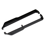
#92002 B64 Side Rails 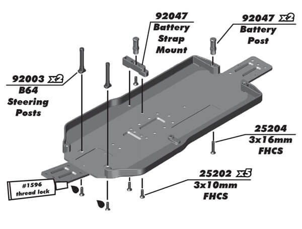 top
Show/Hide Parts

#25202 Screws, 3x10 mm FHCS 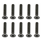
#25204 Screws, 3x16 mm FHCS 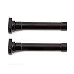
#92003 B64 Steering Posts 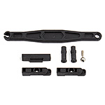
#92047 B64 Battery Mount -
Bag 3, Center Bulkhead
Bags 3.1-3.3 step 1
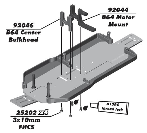 top
Show/Hide Parts
Online Name 
#1596 FT Locking Adhesive 
#25202 Screws, 3x10 mm FHCS 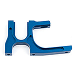
#92044 B64 Motor Mount, aluminum 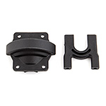
#92046 B64 Center Bulkhead and Cover 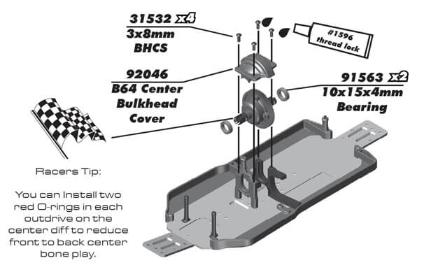 top
Show/Hide Parts
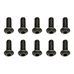
#31532 Screws, 3x0.5x8 mm BHCS 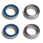
#91563 FT Bearings, 10x15x4 mm 
#92046 B64 Center Bulkhead and Cover -
Bag 4, Steering Rack
Bags 4.1-4.2 step 1
 top
Show/Hide Parts
Online Name 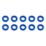
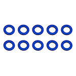
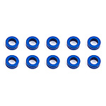
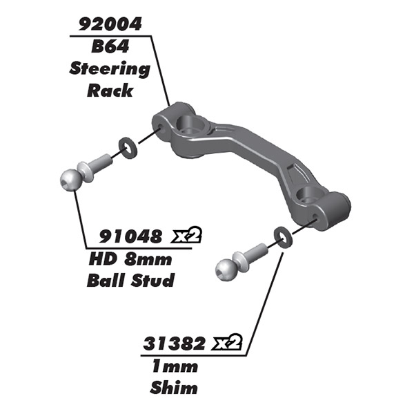
#31382 Ballstud Washers, 5.5x1.0 mm, blue aluminum 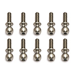
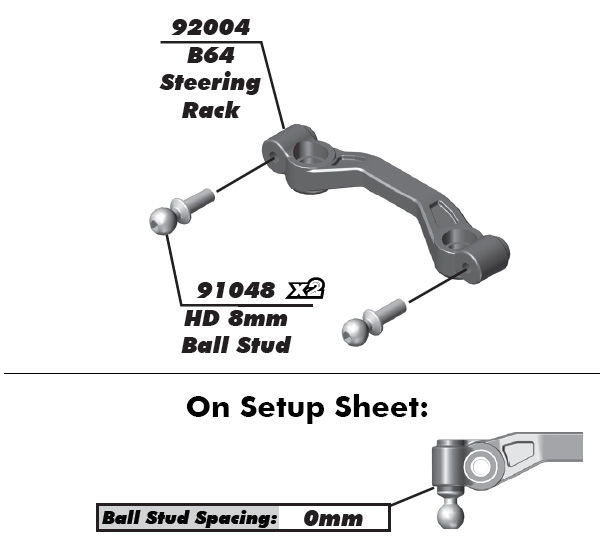
#91048 Heavy-duty Ballstuds, 8 mm 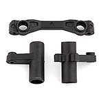
#92004 B64 Bellcranks and Rack 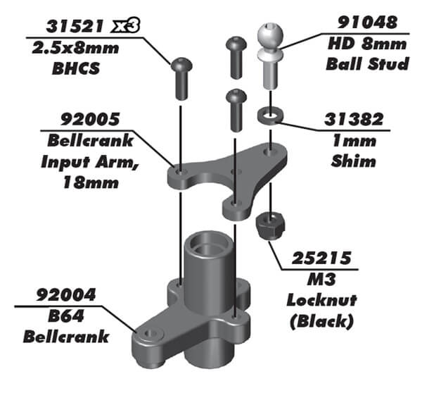 top
Show/Hide Parts
 top
Show/Hide Parts
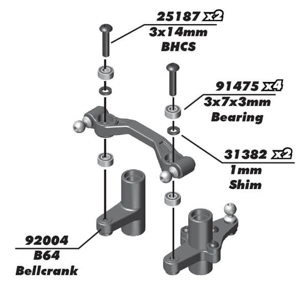
#25187 Locknuts, M3 
#31382 Ballstud Washers, 5.5x1.0 mm, blue aluminum 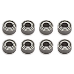
#91475 Bearings, 3x7x3 mm 
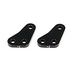
#92004 B64 Bellcranks and Rack 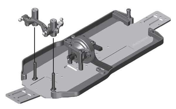
-
Bag 5, Front Gearbox, Tower, Arms
Bags 5.1-5.2 step 1
 Show/Hide Parts

#91563 FT Bearings, 10x15x4 mm 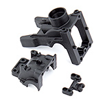
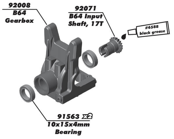
#92008 B64 Gearbox, front and rear 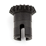
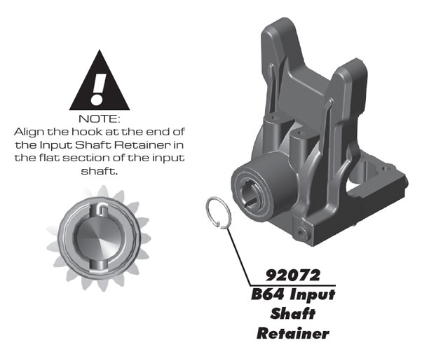
#92071 B64 Input Shaft, 17T Bags 5.1-5.2 step 2
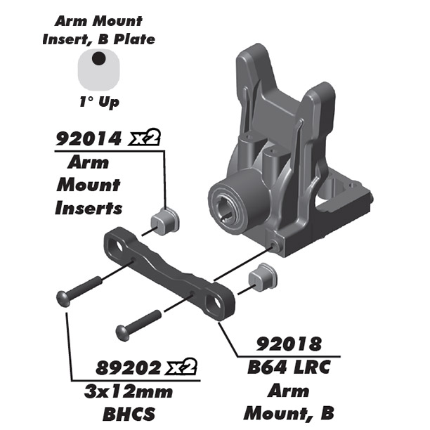 Show/Hide Parts
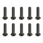
#89202 Screws, 3x12 mm BHCS 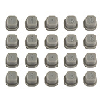
#92014 Arm Mount Inserts 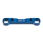
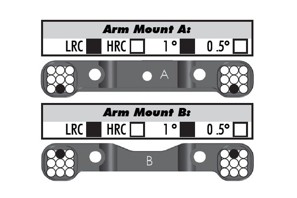
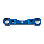
#92018 B64 LRC Arm Mount B, aluminum 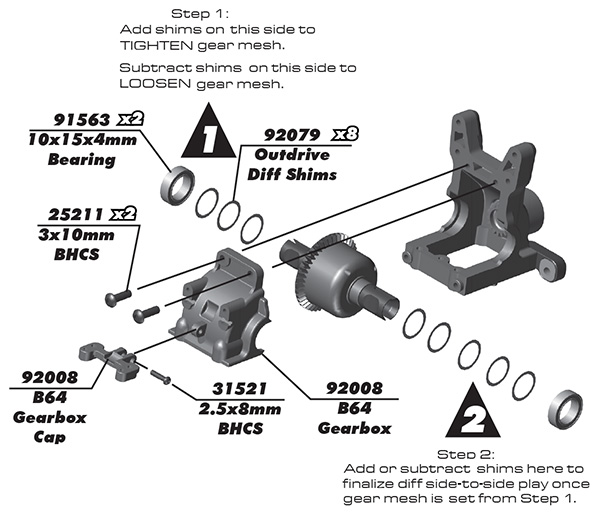 Show/Hide Parts
#6588 Black Grease, 4cc 
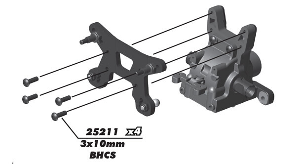
#25211 Screws, 3x10 mm BHCS 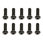
#31521 Screws, M2.5 x 8 BHCS 
#91563 FT Bearings, 10x15x4 mm 
#92079 B64 Diff Shims 
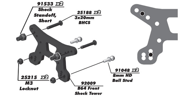
#92008 B64 Gearbox, front and rear Bags 5.1-5.2 step 3
 Show/Hide Parts

#25215 Locknuts, M3 
#25188 Screws, 3x20 mm BHSS 
#91048 Heavy-duty Ballstuds, 8 mm 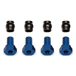
#91533 Shock Bushings, short 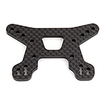
#92009 B64 Front Shock Tower, woven carbon fiber 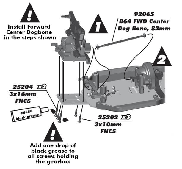
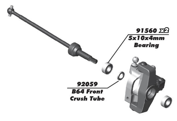
1. Slide dogbone under rack and into the center gearbox outdrive.
Show/Hide Parts
2. Slide front gearbox onto other end of dogbone and fasten gearbox in place.
#6588 Black Grease, 4cc 
#25202 Screws, 3x10 mm FHCS 
#25204 Screws, 3x16 mm FHCS 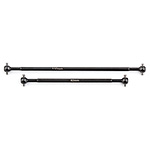
#92065 B64 Center Dogbones, gear diff Bags 5.1-5.2 step 5
 Show/Hide Parts

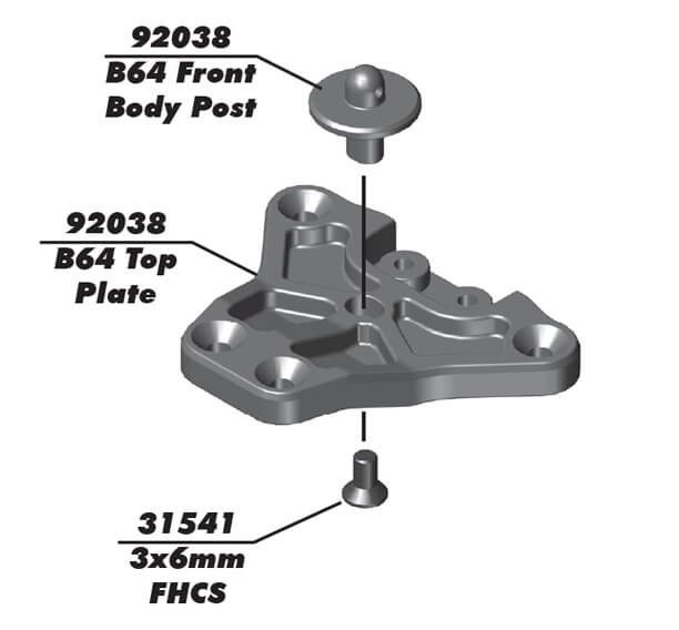
#31541 Screws, 3x0.5x6 mm FHCS 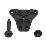
#92038 B64 Top Plate and Body Posts 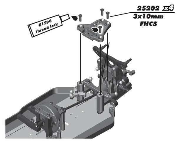
The #1596 threadlock fluid is not included.
Show/Hide Parts
#1596 FT Locking Adhesive 
#25202 Screws, 3x10 mm FHCS 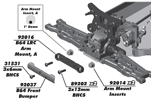 Show/Hide Parts

#6588 Black Grease, 4cc 
#31531 Screws, 3x0.5x6 mm BHCS 
#89202 Screws, 3x12 mm BHCS 
#92014 Arm Mount Inserts 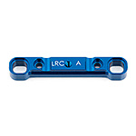
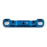
#92016 B64 LRC Arm Mount A, aluminum 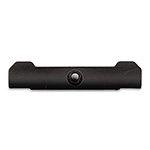
#92037 B64 Front Bumper -
Bag 6, Steering Blocks, CVAs
Bags 6.1-6.2 step 1
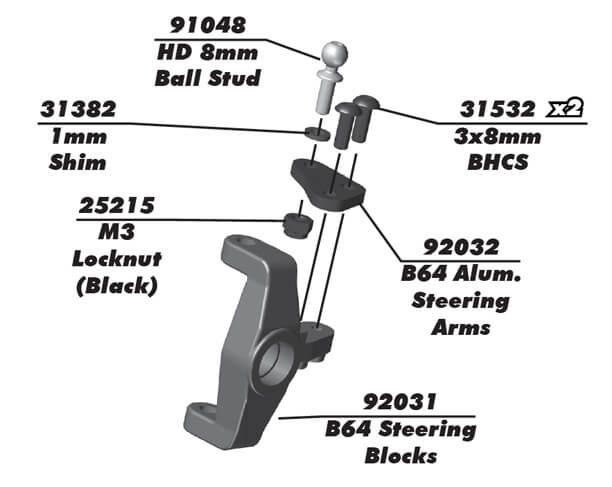 Show/Hide Parts
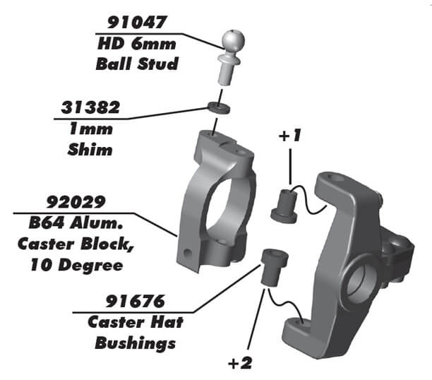 Show/Hide Parts

#31382 Ballstud Washers, 5.5x1.0 mm, blue aluminum 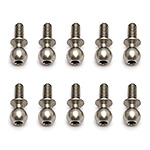
#91047 Heavy-duty Ballstuds, 6 mm 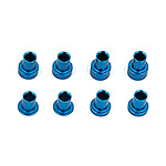
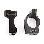
#91676 B6 Caster Hat Bushings 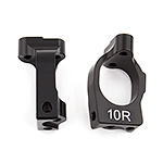
#92029 B64 Aluminum Caster Blocks, 10 deg. Bags 6.1-6.2 step 2
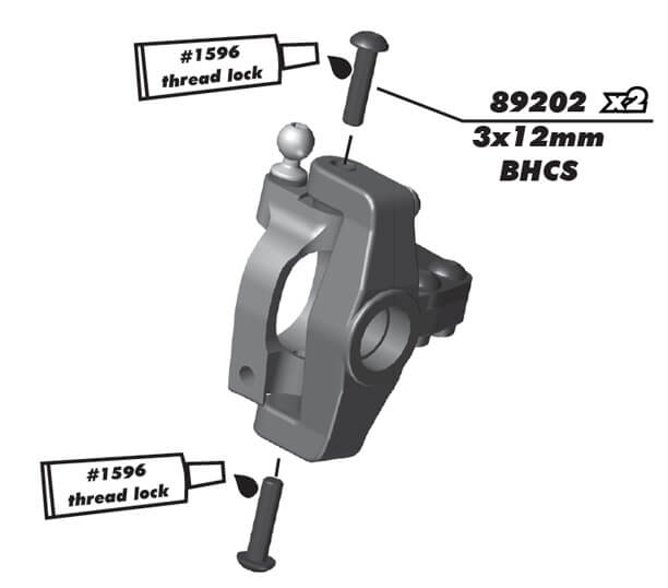
The #1596 threadlock fluid is not included in the kit.
Show/Hide Parts
#1596 FT Locking Adhesive 
#89202 Screws, 3x12 mm BHCS 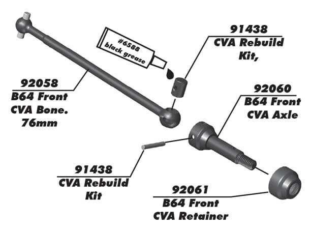 Show/Hide Parts

#6588 Black Grease, 4cc 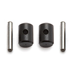
#91438 CVA Rebuild Kit 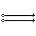
#92058 B64 Front CVA Bones, 76 mm 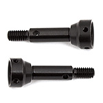
#92060 B64 Front CVA Axles 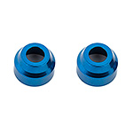
#92061 B64 Front CVA Axle Retainers 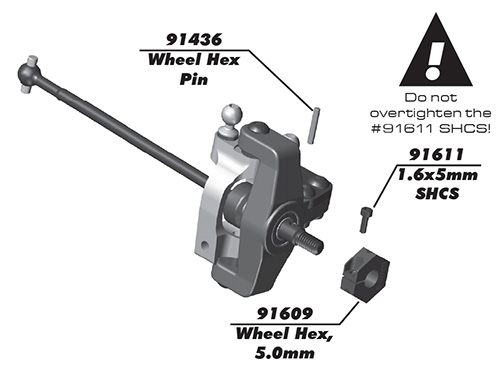 Show/Hide Parts
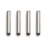
#91436 CVA/Wheel Hex Pins 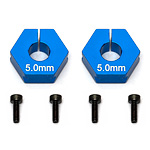
#91609 FT Clamping Wheel Hexes, 5.0mm 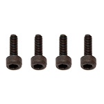
#91611 Screws, 1.6x5 mm SHCS -
Bag 7, Servo
Bags 7.1, 7.2 step 1
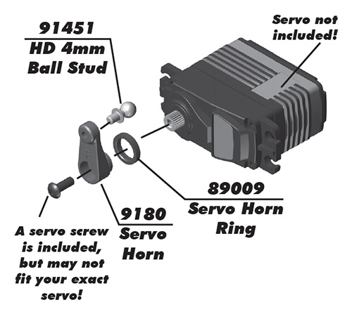
Servo screw is #25211.
top Show/Hide PartsOnline Name 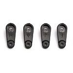
#9180 Servo Horns, molded 
#25211 Screws, 3x10 mm BHCS 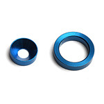
#89009 Servo Support Ring & Washer 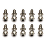
#91451 Heavy-Duty Ballstuds, 4 mm 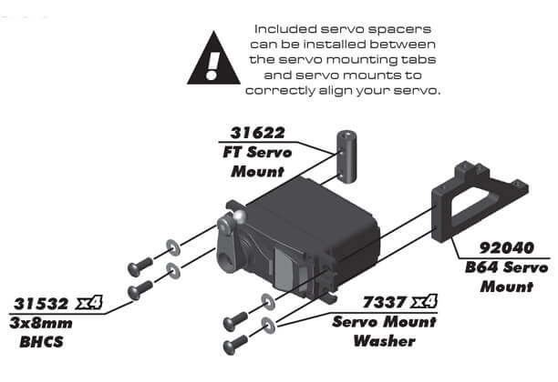 top
Show/Hide Parts
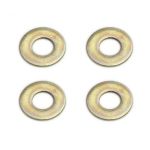
#7337 Washers, .250 x .125 x .015 
#31532 Screws, 3x0.5x8 mm BHCS 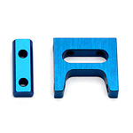
#31622 FT Servo Mount Set 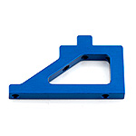
#92040 B64 Servo Mount, aluminum 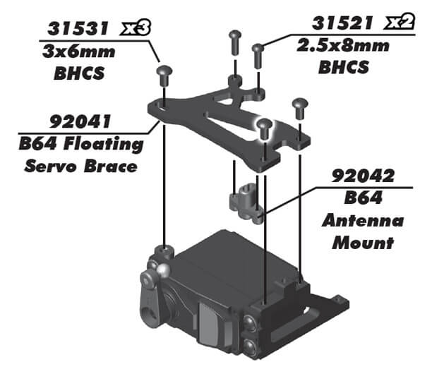 top
Show/Hide Parts

#31521 Screws, M2.5 x 8 BHCS 
#31531 Screws, 3x0.5x6 mm BHCS 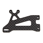
#92041 B64 Floating Servo Brace, graphite 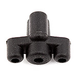
#92042 B64 Antenna Mount Bags 7.1, 7.2 step 2
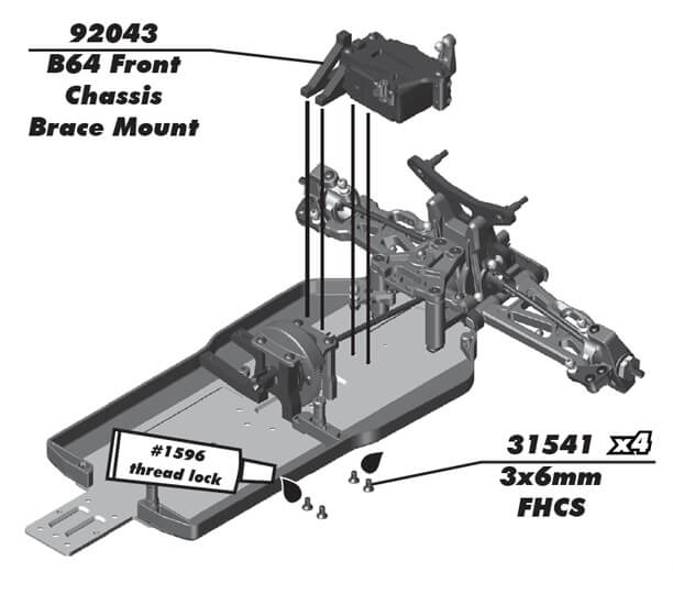 top
Show/Hide Parts

#31541 Screws, 3x0.5x6 mm FHCS 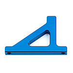
#92043 B64 Front Chassis Brace Mount, aluminum 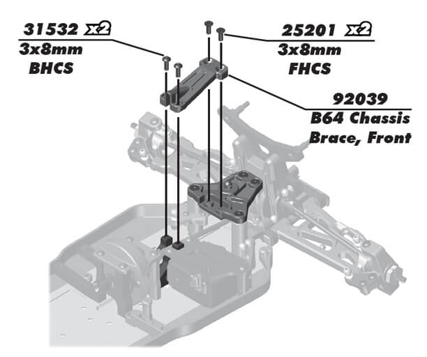 top
Show/Hide Parts

#25201 Screws, 3x8 mm FHCS 
#31532 Screws, 3x0.5x8 mm BHCS 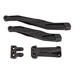
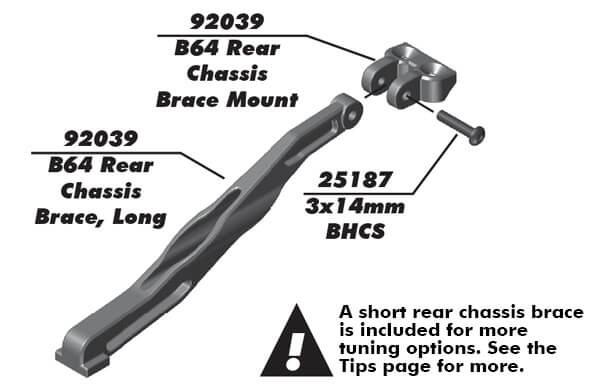
#92039 B64 Chassis Braces -
Bag 8, Rear Gearbox, Tower, Arms
Bags 8.1, 8.2 step 1
 top
Show/Hide Parts
Online Name 
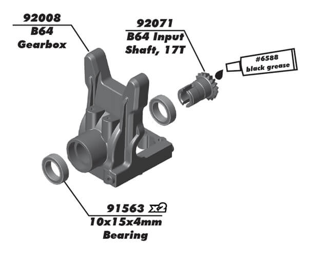
#6588 Black Grease, 4cc 
#91563 FT Bearings, 10x15x4 mm 
#92008 B64 Gearbox, front and rear 
#92071 B64 Input Shaft, 17T Bags 8.1, 8.2 step 2
 top
Show/Hide Parts

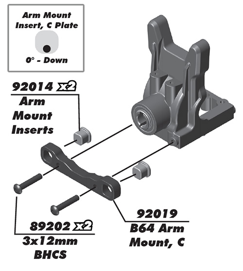
#6588 Black Grease, 4cc 
#89202 Screws, 3x12 mm BHCS 
#92014 Arm Mount Inserts 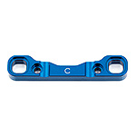
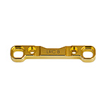
#92019 B64 LRC (Low Roll Center) Arm Mount C, aluminum 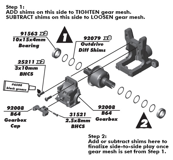 top
Show/Hide Parts

#6588 Black Grease, 4cc 
#25211 Screws, 3x10 mm BHCS 
#31521 Screws, M2.5 x 8 BHCS 
#91563 FT Bearings, 10x15x4 mm 
#92008 B64 Gearbox, front and rear 
#92079 B64 Diff Shims Bags 8.1, 8.2 step 3
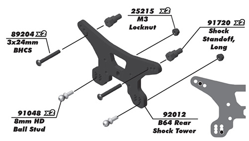 top
Show/Hide Parts

#25215 Locknuts, M3 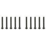
#89204 Screws, 3x24 mm BHCS 
#91048 Heavy-duty Ballstuds, 8 mm 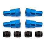
#91720 B6 Shock Bushings, long 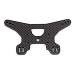
#92012 B64 Rear Shock Tower, graphite Bags 8.1, 8.2 step 4
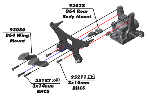 top
Show/Hide Parts

#25211 Screws, 3x10 mm BHCS 
#89202 Screws, 3x12 mm BHCS 
#92038 B64 Top Plate and Body Posts 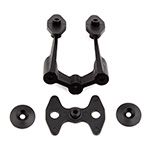
#92050 B64 Wing Mount Set Bags 8.1, 8.2 step 5
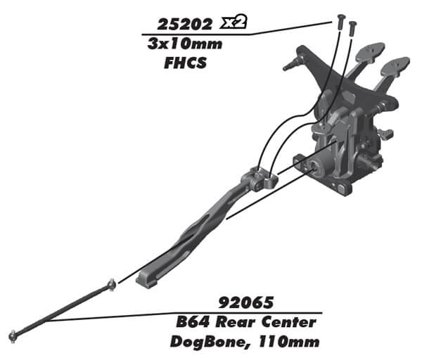 top
Show/Hide Parts

#25202 Screws, 3x10 mm FHCS 
#92065 B64 Center Dogbones, gear diff 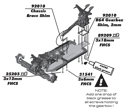 top
Show/Hide Parts

#6588 Black Grease, 4cc 
#25203 Screws, 3x12 mm FHCS 
#31541 Screws, 3x0.5x6 mm FHCS 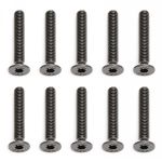
#89209 Screws, 3x18 mm FHCS 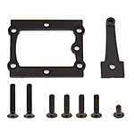
#92010 B64 Gearbox Shim Set 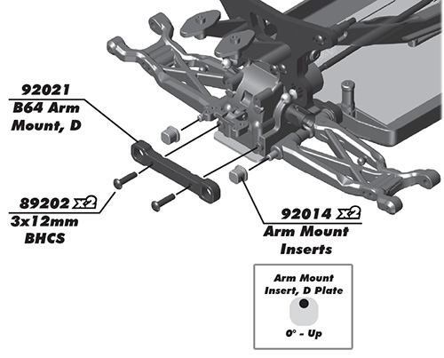 top
Show/Hide Parts

#89202 Screws, 3x12 mm BHCS 
#92014 Arm Mount Inserts 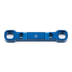
#92021 B64 LRC (Low Roll Center) Arm Mount D, aluminum -
Bag 9, Rear Hub
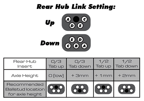
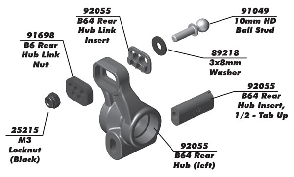
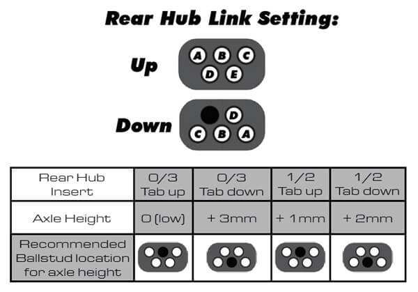
See the Tuning Tips section below for an explanation of this chart.
Bags 9.1-9.2 step 2
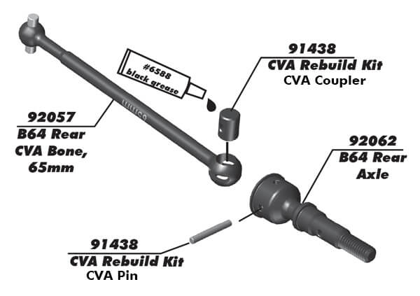
CVA = Constant Velocity Axle.
top Show/Hide PartsOnline Name 
#91438 CVA Rebuild Kit 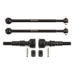
#92057 B64 Rear CVA Set, 65 mm 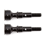
#92062 B64 Rear Axles Bags 9.1-9.2 step 3
 top
Show/Hide Parts
Online Name 
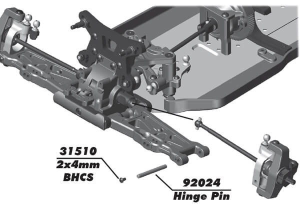
#31510 Screws, 2x0.4x4 mm BHCS 
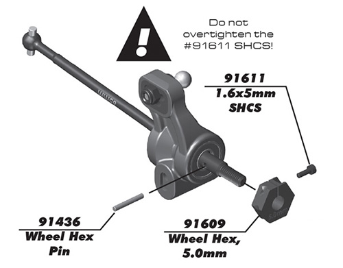
#91609 Factory Team Clamping Wheel Hexes, 5.0mm 
#91611 Screws, 1.6x5 mm SHCS 
#91436 CVA (Constant Velocity Axle)/Wheel Hex Pins -
Bag 10, Anti-roll Bars
Bags 10.1, 10.2 step 1
 top
Show/Hide Parts
Online Name 
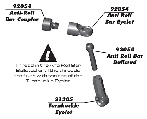
#31305 Turnbuckle Eyelets 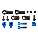
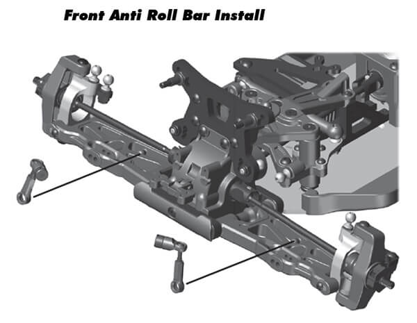
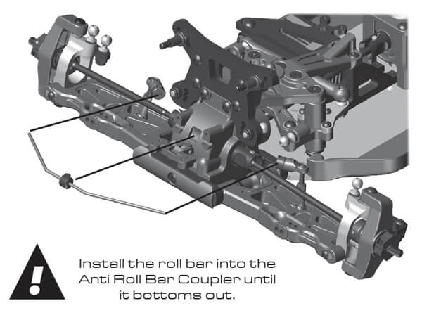
#92054 B64 Anti-roll Bar Hardware 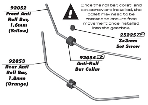
In the note, the collet is referring to the #92054 collar.
top Show/Hide PartsOnline Name 
#25225 Set Screws, 3x3 mm 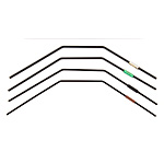
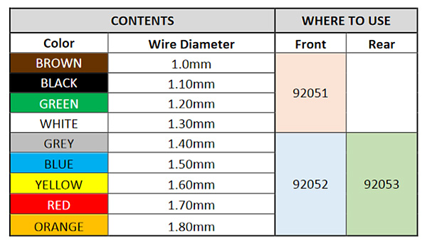
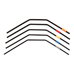
#92051 B64 Anti-roll Bar Set, front, soft 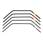
#92053 B64 Anti-roll Bar Set, rear 
#92054 B64 Anti-roll Bar Hardware Bags 10.1, 10.2 step 2
Bags 10.1, 10.2 step 3
 top
Show/Hide Parts

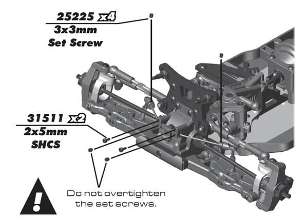
#25225 Set Screws, 3x3 mm 
#31511 Screws, 2x0.4x5 mm SHCS Bags 10.1, 10.2 step 3
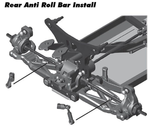
Bags 10.1, 10.2 step 4
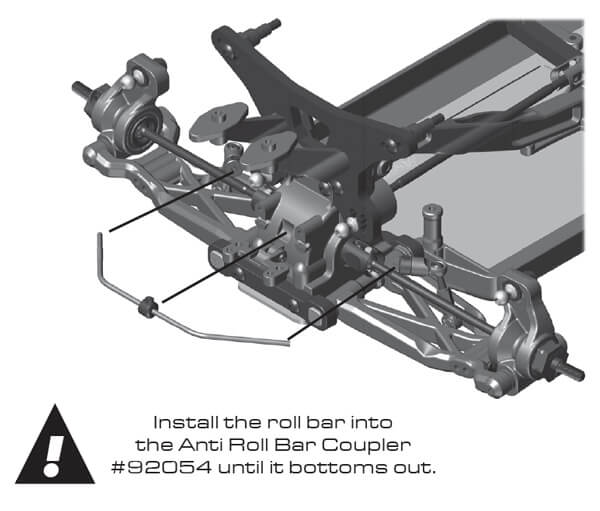
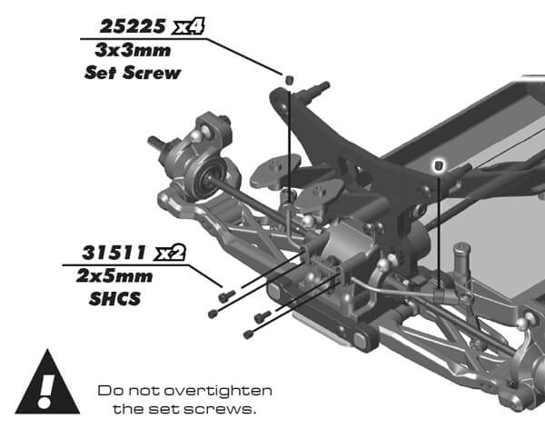 top
Show/Hide Parts

#25225 Set Screws, 3x3 mm 
#31511 Screws, 2x0.4x5 mm SHCS -
Bag 11, Turnbuckles
Bag 11.1 step 2
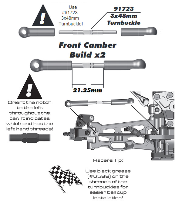
Front Camber Link, from supplementary sheet
top Show/Hide Parts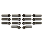
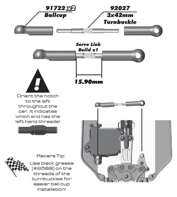
#91722 B6 Ballcups 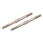
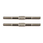
#91723 Turnbuckles, 3x48 mm Bag 11.1 step 3
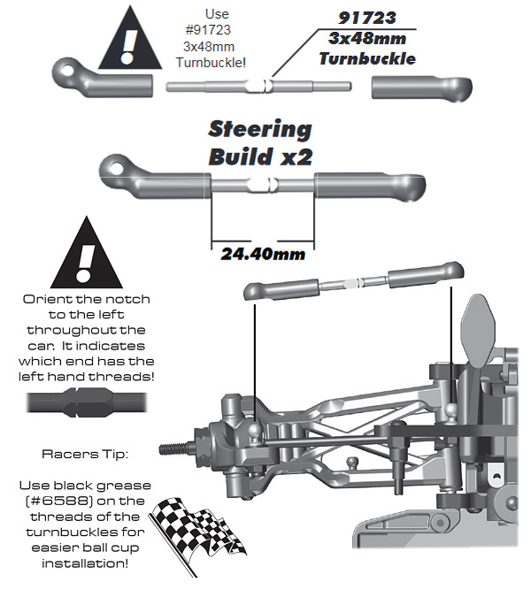
Steering Link, from supplementary sheet
top Show/Hide Parts
#91722 B6 Ballcups 
#91723 Turnbuckles, 3x48 mm Bag 11.1 step 4
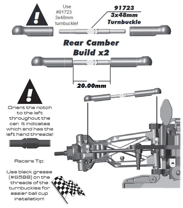
Rear Camber Link, from supplementary sheet
top Show/Hide Parts
#91722 B6 Ballcups 
#91723 Turnbuckles, 3x48 mm -
Bag 12, Shocks
Bags 12.1-12.3 step 1
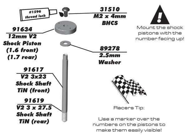 top
Show/Hide Parts
Online Name 
#1596 FT Locking Adhesive 
#31510 Screws, 2x0.4x4 mm BHCS 
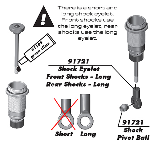
#89278 Washers, 2.5 mm 
#91617 3x23 Shock Shaft V2, TiN 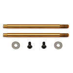
#91619 3x27.5 mm Shock Shafts (V2), TiN 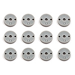
#91634 12mm Shock Pistons, V2 Bags 12.1-12.3 step 2
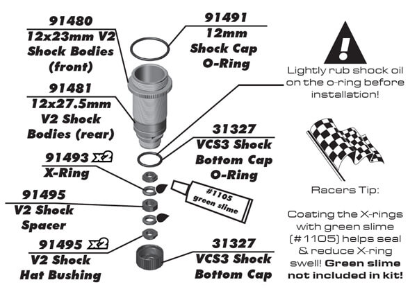 top
Show/Hide Parts
Bags 12.1-12.3 step 3
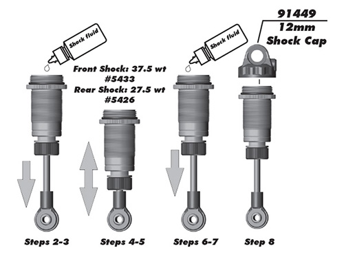
Shock Bleeding Steps
1. Before assembly, install each #91492 bleed screw (see below) 1-2 turns into the shock cap, then remove the screw. This will make it easier when you are bleeding your shocks.
2. Pull shock shaft down.
3. Fill shock body 3/4 full with silicone shock fluid.
4. Slowly move the shock shaft up and down to remove air from under the piston.
5. Wait for bubbles to come to surface.
6. Fill shock body to top with silicone shock fluid.
7. Place a drop of oil in the cap and on cap threads.
8. Install cap (without bleeding screw) and tighten completely.
9. Slowly compress shaft all the way to bleed excess silicone shock fluid out the hole in the cap. Use a rag around shock to catch excess fluid.
10. Install the #91492 M2x4mm button head screw (see below) until snug while shaft is fully compressed.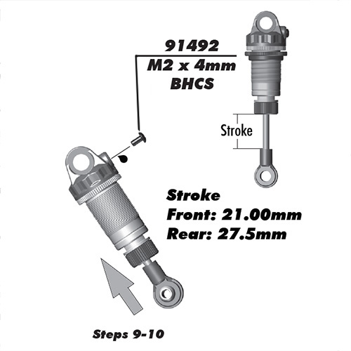 top
Show/Hide Parts
#5422 FT Silicone Shock Fluid, 30wt (350 cSt) 
#5423 FT Silicone Shock Fluid, 40wt (500 cSt) 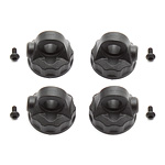
#91449 12 mm V2 Composite Shock Caps 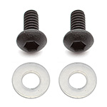
#91492 12 mm V2 Bleeder Gaskets Bags 12.1-12.3 step 4
 top
Show/Hide Parts
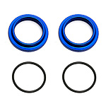
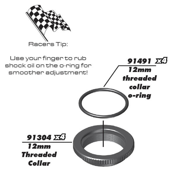
#91304 FT 12 mm Threaded Collars 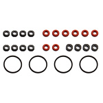
#91491 12 mm V2 Shock Rebuild 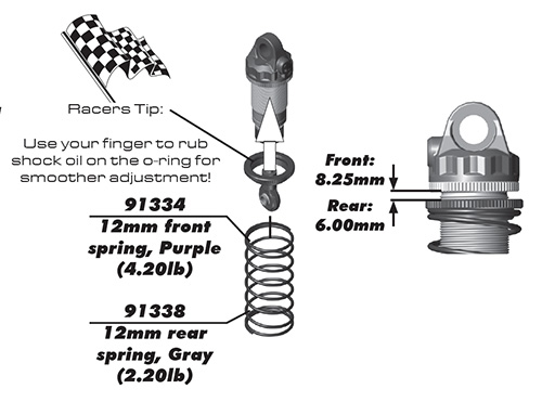 top
Show/Hide Parts
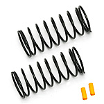
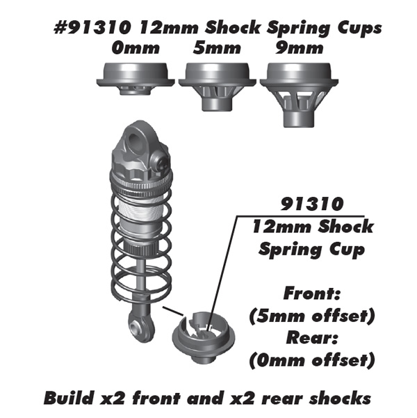
#91331 FT 12mm Front Springs, yellow, 3.75 lb 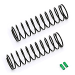
#91336 FT 12mm Rear Springs, green, 2.00 lb Bags 12.1-12.3 step 5
 top
Show/Hide Parts
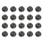
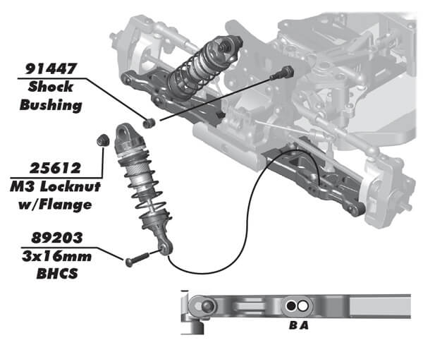
#25612 Locknuts, M3 with flange 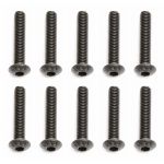
#89203 Screws, 3x16 mm BHCS 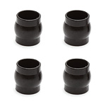
#91447 Shock Bushing Balls 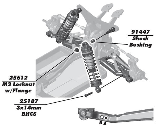 top
Show/Hide Parts

#25612 Locknuts, M3 with flange 
#25187 Screws, 3x14 mm BHCS 
#91447 Shock Bushing Balls -
Bag 13, Electronics
Bags 13.1-13.3 step 1
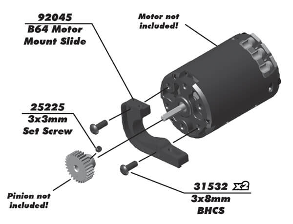
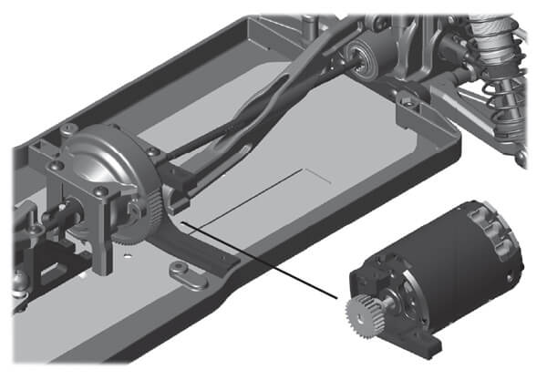 top
Show/Hide Parts
Online Name 
#25225 Set Screws, 3x3 mm 
#31532 Screws, 3x0.5x8 mm BHCS 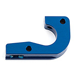
#92045 B64 Motor Mount Slide, aluminum Bags 13.1-13.3 step 2
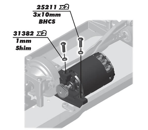 top
Show/Hide Parts

#25211 Screws, 3x10 mm BHCS 
#31382 Ballstud Washers, 5.5x1.0 mm, blue aluminum 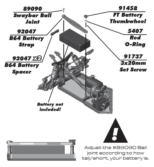 top
Show/Hide Parts
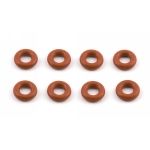
#5407 Red O-Rings 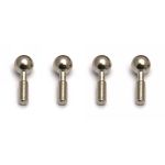
#89090 Swaybar Ball Joints 
#91458 FT Battery Strap Thumbwheels 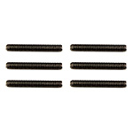
#91737 Set Screws, M3x20 mm 
#92047 B64 Battery Mount -
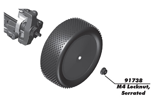
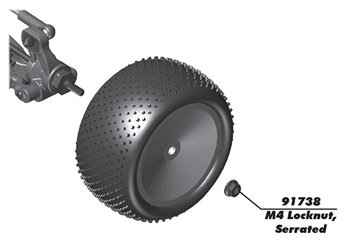
Bag 13, Wheels and Tires
-
Bag 13, Body and Wing
Bags 13.1-13.3 step 6
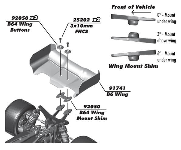
See Tips for painting the body in the Tuning Tips below
top Show/Hide Parts
#25202 Screws, 3x10 mm FHCS 
#91741 B6 Wing 
#92050 B64 Wing Mount Set
 Show/Hide Parts
